

The main shortcoming of water power as an energy resource for irrigation is that it is only available for convenient use in a limited number of locations having suitable flows and heads to engineer an effective site. Also, most regions with hydro-potential tend also to have plentiful rainfall, which often makes irrigation a low priority as a hydro-power application. However, despite these drawbacks, there are many areas where rainfall is seasonal (eg. where water can usefully be applied during the hot dry summer months to gain an extra crop or to increase yields and, similarly, in mountainous areas, where snow-melt water often provides some limited hydro-potential in the dry summer season). However, steep hydraulic gradients in hilly country generally allow any valley floor areas to be gravity irrigated by digging contoured canals, which take water from a stream and direct it along the side of a valley at a lesser hydraulic gradient then the main stream. This practice is of course widespread in much of the central Asian massif. When gravity does the work, pumping techniques are generally not needed.

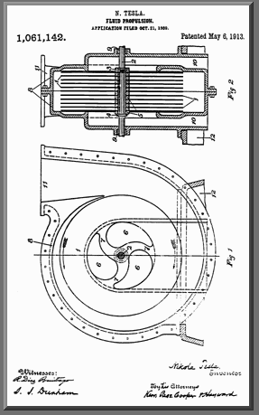
On October 21st, 1909, Nikola Tesla (an inventor of many ingenious items) filed a patent for a pump which uses smooth rotating disks inside a volute casing.
Tesla's novel method of "fluid propulsion" was based on two basic principals of physics: "adhesion and viscosity".
In the patent (which he received May 6th, 1913) Tesla began by pointing out the benefits of a smooth transition of energy:
"In the practical application of mechanical power based on the use of fluid as the vehicle of energy, it has been demonstrated that, in order to attain the highest economy, the changes in velocity and direction of movement of the fluid should be as gradual as possible."
His device accomplishes this by harnessing the "internal forces opposing molecular separation" and "the shock of the fluid against the asperities of the solid substance". (Asperities are surface deformities, which even the smoothest disk will have.)
 Images & quotes from U.S. patent #1,061,142, May 6th, 1913. The pump disks are keyed to a single shaft (a dark rod in the top drawing from the patent). The inlets for the fluid are shown in light blue in the upper drawing.
 Each disk has holes cut in the center "preferably curved, as shown". We have highlighted the holes in light blue in the lower drawing.
The patent states that to reduce clogging, a solid disk or disks ("each in its own casing") can be used. Also, the pump can be staged for increased pressure, using the output of one disk as the input to the next, in series, on one shaft.
With a rotational force applied to the shaft, rotating the keyed disks, the fluid rotates as well and moves towards the outer edge of the disks. In the lower drawing the fluid spirals out in a counter-clockwise direction.
The fluid might complete one or more revolutions, or less than a revolution, before reaching the outer edges of the disks, depending on the viscosity of the fluid, the speed of rotation, the width between the disks, and other factors.
 Here we have highlighted in red, the exit path of the fluid through the volute, after it has spiralled out from the center as the disks rotate. In the bottom drawing the fluid and the disks all rotate in a counterclockwise direction.
 According to Tesla's patent:
"In general, the spacing [of the disks] should be such that the entire mass of the fluid, before leaving the runner [the disks], is accelerated to a nearly uniform velocity, not much below the periphery of the disks under normal working conditions and almost equal to it when the outlet is closed and the particles move in concentric circles."
The author once saw a delightful working model of this pump. It was made out of stiff paper and tape.
Copies of patents are available from the U.S. Patent office for a small fee.
http://www.animatedsoftware.com


