A GM C Sierra with an Eaton G80 locking differential traverses the ditch simulation. Click image to enlarge
With the locking axle, the vehicle was driven slowly on the roller and the wheel spun freely. By accelerating slightly so the spinning wheel is turning about 100 rpm or about 13 km/h, centrifugal weights in the differential latch to a locking mechanism that forces the differential gears to spread apart and engage clutches in the sides of the differential. Within one turn of the wheel, the clutches lock both sides together and the truck drives over the obstacle with ease. I have pulled out of icy parking spots with a GM vehicle equipped with an Eaton locking axle many times when I would have been stuck without one.
Another demonstration simulated driving the trucks over a ditch at an angle. When the truck was in the middle of the transition, one rear wheel and one front wheel had almost no load on them. With the four-wheel drive vehicles, both the one front and one rear wheel without load would spin and the truck would move no further. It was stuck. Even with four-wheel traction control, the vehicle remained stuck because the computer would reduce power at the same time it braked the spinning wheels. There still wasn’t enough torque transfer to the wheels with traction to get the truck moving.
As the two-wheel drive truck with the Eaton locking axle reached the transition, the unloaded rear wheel began to spin but within one turn of the spinning wheel the axle had locked and the truck drove through. It demonstrated that a locking axle in a two-wheel drive vehicle can perform better than four-wheel drive.
Eaton G80 locking differential. Click image to enlarge
Eaton’s locking differential is used for low speed traction. At speeds above about 30 km/h, a centrifugal weight disables the locking mechanism so that the wheels can turn independently. Unlike limited slip or Positrac differentials which have spring loaded clutches that are engaged at all speeds, the locking differential now allows one wheel to spin. This ensures vehicle stability if you encounter black ice on the highway. If both wheels were locked, they would both spin and the rear of the vehicle would have no stability. Without being locked, only one wheel spins and the other maintains some traction.
Traction at low speeds with the stability of an open differential at higher speeds: Eaton offers this for only about $300 as an option on GM trucks. It’s definitely worth the money.
Jim Kerr is a master automotive mechanic and teaches automotive technology. He has been writing automotive articles for fifteen years for newspapers and magazines in Canada and the United States, and is a member of the Automobile Journalists Association of Canada (AJAC).
Technology
Adhitz 728
Adhitz
Wednesday, January 19, 2011
Sparks Fly
Sparks Fly |
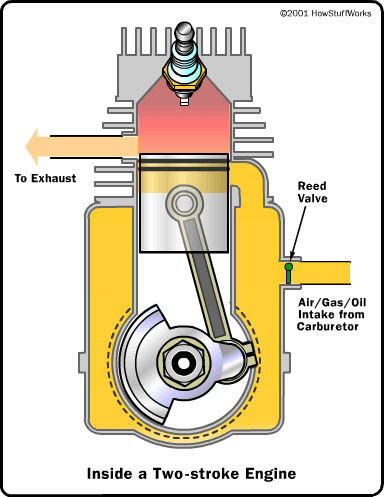
You can understand a two-stroke engine by watching each part of the cycle. Start with the point where the spark plug fires. Fuel and air in the cylinder have been compressed, and when the spark plug fires the mixture ignites. The resulting explosion drives the piston downward. Note that as the piston moves downward, it is compressing the air/fuel mixture in the crankcase. As the piston approaches the bottom of its stroke, the exhaust port is uncovered. The pressure in the cylinder drives most of the exhaust gases out of cylinder, as shown here: |
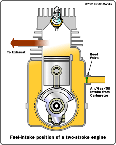
Fuel Intake |
As the piston finally bottoms out, the intake port is uncovered. The piston's movement has pressurized the mixture in the crankcase, so it rushes into the cylinder, displacing the remaining exhaust gases and filling the cylinder with a fresh charge of fuel, as shown here: Note that in many two-stroke engines that use a cross-flow design, the piston is shaped so that the incoming fuel mixture doesn't simply flow right over the top of the piston and out the exhaust port. |
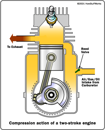
The Compression Stroke |
Now the momentum in the crankshaft starts driving the piston back toward the spark plug for the compression stroke. As the air/fuel mixture in the piston is compressed, a vacuum is created in the crankcase. This vacuum opens the reed valve and sucks air/fuel/oil in from the carburetor. Once the piston makes it to the end of the compression stroke, the spark plug fires again to repeat the cycle. It's called a two-stoke engine because there is a compression stroke and then a combustion stroke. In a four-stroke engine, there are separate intake, compression, combustion and exhaust strokes. You can see that the piston is really doing three different things in a two-stroke engine:
If you have ever used a two-stroke engine, you know that you have to mix special two-stroke oil in with the gasoline. Now that you understand the two-stroke cycle you can see why. In a four-stroke engine, the crankcase is completely separate from the combustion chamber, so you can fill the crankcase with heavy oil to lubricate the crankshaft bearings, the bearings on either end of the piston's connecting rod and the cylinder wall. In a two-stroke engine, on the other hand, the crankcase is serving as a pressurization chamber to force air/fuel into the cylinder, so it can't hold a thick oil. Instead, you mix oil in with the gas to lubricate the crankshaft, connecting rod and cylinder walls. If you forget to mix in the oil, the engine isn't going to last very long! |
Disadvantages of the Two-stroke |
You can now see that two-stroke engines have two important advantages over four-stroke engines: They are simpler and lighter, and they produce about twice as much power. So why do cars and trucks use four-stroke engines? There are four main reasons:
These disadvantages mean that two-stroke engines are used only in applications where the motor is not used very often and a fantastic power-to-weight ratio is important. In the meantime, manufacturers have been working to shrink and lighten four-stroke engines, and you can see that research coming to market in a variety of new marine and lawn-care products. http://www.chooseindia.com |
http://tariqhafez.blogspot.com/
May harm your computer
A Compressed air car is a car that uses a motor powerd by compressed air. . The compressed-air engine is used to activate an alternator, which extends . . presented on the Beyond Tomorrow programme; The Science Channel Video Report .
While the piston is close to Top Dead Center, the compressed air–fuel . . of car components in action; Video from inside a four-stroke engine cylinder. .
Tags: compressed, air, Pneumatic, engine, hybrid, vehicle, car. Description: . Regular videos. 2009 Geneva Motor Show: MDI Compressed Air Car - Exclusive .
This site may harm your computer.
Related videos. More in Others - Auto · Car engine configuration and types .
We will make Air Car Conversions and Compressed Air Engines a viable and common . Initial experiments started Sept 06. Air Lawn Mower Engine Video .
23 May 2008 . air-car-engine.jpg. This is another look at the “Air Car†that I . the oil pumping Rockfellers won't decide to charge us for air. VIDEO-> .
1 post - 1 author - Last post: 25 Nov6 Jul 2008 The Compressed Air Engine and Air Car. . used in this video, Added to queue Air Car Water Car Fuel Clean Motor Save Gas Bes. .
19 Feb 2010 . I would think using compressed air with a gas engine could work ok, as one produces . Video: MDI Air car (compressed air powered), Lazarus .
http://wn.com/Air_Car_by_Guy_Negre's_compressed_air_technolgy_BBC; Email this video; Sms this video. Guy Negre of MDI Air Car engine that runs on compressed .
This site may harm your computer.
A compressed air engine could be used to power a car, if you had a tank large enough to store it. . See all Fuel Consumption articles. Hybrid Car Videos .
PHOTO of March 2008 MDI Compressed Air Engine (CAE) in NY Motor Show . On TV MDI's in Air car featured in 8 minute video on Indianpad.com ('07) .
4 Apr 2008 . There are several other players in the Compressed Air Engine Market. former partner is running Air Car Factories, but has yet to find a .
31 Oct 2010 . 1.3.1 Engine; 1.3.2 Energy Storage. 1.4 Videos/Photos. 1.4.1 A car that runs 200 miles on compressed air; 1.4.2 The Air Car .
The six pistons in the Air Car's engine are pushed by compressed air rather than . . Compressed Air Car Video. The people of this world are now demanding .
17 May 2008 . Propulsion technology of the AirCar's engine was developed by the . Compressed air is just a way of carrying energy so you have to pay for .
10 Apr 2008 . Compressed Air Car Video. The people of this world are now demanding . see a solar powered Stirling engine vehicle pave the way forward. .
The CAT car is powered by a thermodynamic motor that runs on air compressed to 4350 psi. When the air enters the engine it expands and .
15 Mar 2007 . This compressed air car technology was interesting to me, . it's on Google Video (you search Robert Newman Oil – but you knew that, . couldn't the car have a built in air compressor that runs from the air engine, .
5 Aug 2010 . Air Car Water Car Fuel Clean Motor Save Gas Best Engine . . It is, of course, possible to power a car on compressed air, I mean at least for the 5 miles, . Mandala Quartz Crystal Singing Bowl Energy Healing Video .
8 Oct 2008 . Many of you haven't heard of the compressed air car - but chances . An Air Car Engine weights one-third that of a combustion engine · Hybrid . . Air Car Videos 2. Clearly, a daunting uphill climb is needed to oust a .
17 posts - 8 authors - Last post: 31 May 2007The Air Car uses compressed air to push its engine's pistons. . Watch the video I posted, it addresses car accidents impacting the scuba .
Test driving an MDI, compressed air car Electric-Car Examiner.com - 10 October . . The MDI air car engines have the capability to become one of the largest .
Compressed Air Car with. Quasi-turbine Pneumatic Engine (Quasi-turbine air motor). Since the Quasi-turbine is a pure expansion engine (which the Wankel is not, .
http://liveitupempire.com/
Output Shaft
The output shaft has round lobes mounted eccentrically, meaning that they are offset from the center line of the shaft. Each rotor fits over one of these lobes. The lobe acts sort of like the crankshaft in a piston engine. As the rotor follows its path around the housing, it pushes on the lobes. Since the lobes are mounted eccentric to the output shaft, the force that the rotor applies to the lobes creates torque in the shaft, causing it to spin.
Now let's take a look at how these parts are assembled and how it produces power.
The two end layers contain the seals and bearings for the output shaft. They also seal in the two sections of housing that contain the rotors. The inside surfaces of these pieces are very smooth, which helps the seals on the rotor do their job. An intake port is located on each of these end pieces.
The next layer in from the outside is the oval-shaped rotor housing, which contains the exhaust ports. This is the part of the housing that contains the rotor.
The center piece contains two intake ports, one for each rotor. It also separates the two rotors, so its outside surfaces are very smooth.
In the center of each rotor is a large internal gear that rides around a smaller gear that is fixed to the housing of the engine. This is what determines the orbit of the rotor. The rotor also rides on the large circular lobe on the output shaft.
Next, we'll see how the engine actually makes power.
The heart of a rotary engine is the rotor. This is roughly the equivalent of the pistons in a piston engine. The rotor is mounted on a large circular lobe on the output shaft. This lobe is offset from the centerline of the shaft and acts like the crank handle on a winch, giving the rotor the leverage it needs to turn the output shaft. As the rotor orbits inside the housing, it pushes the lobe around in tight circles, turning three times for every one revolution of the rotor.
As the rotor moves through the housing, the three chambers created by the rotor change size. This size change produces a pumping action. Let's go through each of the four strokes of the engine looking at one face of the rotor.
Intake
The intake phase of the cycle starts when the tip of the rotor passes the intake port. At the moment when the intake port is exposed to the chamber, the volume of that chamber is close to its minimum. As the rotor moves past the intake port, the volume of the chamber expands, drawing air/fuel mixture into the chamber.
When the peak of the rotor passes the intake port, that chamber is sealed off and compression begins.
Compression
As the rotor continues its motion around the housing, the volume of the chamber gets smaller and the air/fuel mixture gets compressed. By the time the face of the rotor has made it around to the spark plugs, the volume of the chamber is again close to its minimum. This is when combustion starts.
Combustion
Most rotary engines have two spark plugs. The combustion chamber is long, so the flame would spread too slowly if there were only one plug. When the spark plugs ignite the air/fuel mixture, pressure quickly builds, forcing the rotor to move.
The pressure of combustion forces the rotor to move in the direction that makes the chamber grow in volume. The combustion gases continue to expand, moving the rotor and creating power, until the peak of the rotor passes the exhaust port.
Exhaust
Once the peak of the rotor passes the exhaust port, the high-pressure combustion gases are free to flow out the exhaust. As the rotor continues to move, the chamber starts to contract, forcing the remaining exhaust out of the port. By the time the volume of the chamber is nearing its minimum, the peak of the rotor passes the intake port and the whole cycle starts again.
The neat thing about the rotary engine is that each of the three faces of the rotor is always working on one part of the cycle -- in one complete revolution of the rotor, there will be three combustion strokes. But remember, the output shaft spins three times for every complete revolution of the rotor, which means that there is one combustion stroke for each revolution of the output shaft.
Fewer Moving Parts
The rotary engine has far fewer moving parts than a comparable four-stroke piston engine. A two-rotor rotary engine has three main moving parts: the two rotors and the output shaft. Even the simplest four-cylinder piston engine has at least 40 moving parts, including pistons, connecting rods, camshaft, valves, valve springs, rockers, timing belt, timing gears and crankshaft.
This minimization of moving parts can translate into better reliability from a rotary engine. This is why some aircraft manufacturers (including the maker of Skycar) prefer rotary engines to piston engines.
Smoother
All the parts in a rotary engine spin continuously in one direction, rather than violently changing directions like the pistons in a conventional engine do. Rotary engines are internally balanced with spinning counterweights that are phased to cancel out any vibrations.
The power delivery in a rotary engine is also smoother. Because each combustion event lasts through 90 degrees of the rotor's rotation, and the output shaft spins three revolutions for each revolution of the rotor, each combustion event lasts through 270 degrees of the output shaft's rotation. This means that a single-rotor engine delivers power for three-quarters of each revolution of the output shaft. Compare this to a single-cylinder piston engine, in which combustion occurs during 180 degrees out of every two revolutions, or only a quarter of each revolution of the crankshaft (the output shaft of a piston engine).
Slower
Since the rotors spin at one-third the speed of the output shaft, the main moving parts of the engine move slower than the parts in a piston engine. This also helps with reliability.
Challenges
There are some challenges in designing a rotary engine:
http://tariqhafez.blogspot.com/
Now let's take a look at how these parts are assembled and how it produces power.
Rotary Engine Assembly
A rotary engine is assembled in layers. The two-rotor engine we took apart has five main layers that are held together by a ring of long bolts. Coolant flows through passageways surrounding all of the pieces. One of the two end pieces of a two-rotor Wankel engine |
The part of the rotor housing that holds the rotors (Note the exhaust port location.) |
The center piece contains another intake port for each rotor. |
Next, we'll see how the engine actually makes power.
Rotary Engine Power
Rotary engines use the four-stroke combustion cycle, which is the same cycle that four-stroke piston engines use. But in a rotary engine, this is accomplished in a completely different way. As the rotor moves through the housing, the three chambers created by the rotor change size. This size change produces a pumping action. Let's go through each of the four strokes of the engine looking at one face of the rotor.
Intake
The intake phase of the cycle starts when the tip of the rotor passes the intake port. At the moment when the intake port is exposed to the chamber, the volume of that chamber is close to its minimum. As the rotor moves past the intake port, the volume of the chamber expands, drawing air/fuel mixture into the chamber.
When the peak of the rotor passes the intake port, that chamber is sealed off and compression begins.
Compression
As the rotor continues its motion around the housing, the volume of the chamber gets smaller and the air/fuel mixture gets compressed. By the time the face of the rotor has made it around to the spark plugs, the volume of the chamber is again close to its minimum. This is when combustion starts.
Combustion
Most rotary engines have two spark plugs. The combustion chamber is long, so the flame would spread too slowly if there were only one plug. When the spark plugs ignite the air/fuel mixture, pressure quickly builds, forcing the rotor to move.
The pressure of combustion forces the rotor to move in the direction that makes the chamber grow in volume. The combustion gases continue to expand, moving the rotor and creating power, until the peak of the rotor passes the exhaust port.
Exhaust
Once the peak of the rotor passes the exhaust port, the high-pressure combustion gases are free to flow out the exhaust. As the rotor continues to move, the chamber starts to contract, forcing the remaining exhaust out of the port. By the time the volume of the chamber is nearing its minimum, the peak of the rotor passes the intake port and the whole cycle starts again.
The neat thing about the rotary engine is that each of the three faces of the rotor is always working on one part of the cycle -- in one complete revolution of the rotor, there will be three combustion strokes. But remember, the output shaft spins three times for every complete revolution of the rotor, which means that there is one combustion stroke for each revolution of the output shaft.
Differences and Challenges
There are several defining characteristics that differentiate a rotary engine from a typical piston engine. Fewer Moving Parts
The rotary engine has far fewer moving parts than a comparable four-stroke piston engine. A two-rotor rotary engine has three main moving parts: the two rotors and the output shaft. Even the simplest four-cylinder piston engine has at least 40 moving parts, including pistons, connecting rods, camshaft, valves, valve springs, rockers, timing belt, timing gears and crankshaft.
This minimization of moving parts can translate into better reliability from a rotary engine. This is why some aircraft manufacturers (including the maker of Skycar) prefer rotary engines to piston engines.
Smoother
All the parts in a rotary engine spin continuously in one direction, rather than violently changing directions like the pistons in a conventional engine do. Rotary engines are internally balanced with spinning counterweights that are phased to cancel out any vibrations.
The power delivery in a rotary engine is also smoother. Because each combustion event lasts through 90 degrees of the rotor's rotation, and the output shaft spins three revolutions for each revolution of the rotor, each combustion event lasts through 270 degrees of the output shaft's rotation. This means that a single-rotor engine delivers power for three-quarters of each revolution of the output shaft. Compare this to a single-cylinder piston engine, in which combustion occurs during 180 degrees out of every two revolutions, or only a quarter of each revolution of the crankshaft (the output shaft of a piston engine).
Slower
Since the rotors spin at one-third the speed of the output shaft, the main moving parts of the engine move slower than the parts in a piston engine. This also helps with reliability.
Challenges
There are some challenges in designing a rotary engine:
- Typically, it is more difficult (but not impossible) to make a rotary engine meet U.S. emissions regulations.
- The manufacturing costs can be higher, mostly because the number of these engines produced is not as high as the number of piston engines.
- They typically consume more fuel than a piston engine because the thermodynamic efficiency of the engine is reduced by the long combustion-chamber shape and low compression ratio.
http://tariqhafez.blogspot.com/
Output Shaft
The output shaft has round lobes mounted eccentrically, meaning that they are offset from the centerline of the shaft. Each rotor fits over one of these lobes. The lobe acts sort of like the crankshaft in a piston engine. As the rotor follows its path around the housing, it pushes on the lobes. Since the lobes are mounted eccentric to the output shaft, the force that the rotor applies to the lobes creates torque in the shaft, causing it to spin.
Now let's take a look at how these parts are assembled and how it produces power.
The two end layers contain the seals and bearings for the output shaft. They also seal in the two sections of housing that contain the rotors. The inside surfaces of these pieces are very smooth, which helps the seals on the rotor do their job. An intake port is located on each of these end pieces.
The next layer in from the outside is the oval-shaped rotor housing, which contains the exhaust ports. This is the part of the housing that contains the rotor.
The center piece contains two intake ports, one for each rotor. It also separates the two rotors, so its outside surfaces are very smooth.
In the center of each rotor is a large internal gear that rides around a smaller gear that is fixed to the housing of the engine. This is what determines the orbit of the rotor. The rotor also rides on the large circular lobe on the output shaft.
Next, we'll see how the engine actually makes power.
The heart of a rotary engine is the rotor. This is roughly the equivalent of the pistons in a piston engine. The rotor is mounted on a large circular lobe on the output shaft. This lobe is offset from the centerline of the shaft and acts like the crank handle on a winch, giving the rotor the leverage it needs to turn the output shaft. As the rotor orbits inside the housing, it pushes the lobe around in tight circles, turning three times for every one revolution of the rotor.
As the rotor moves through the housing, the three chambers created by the rotor change size. This size change produces a pumping action. Let's go through each of the four strokes of the engine looking at one face of the rotor.
Intake
The intake phase of the cycle starts when the tip of the rotor passes the intake port. At the moment when the intake port is exposed to the chamber, the volume of that chamber is close to its minimum. As the rotor moves past the intake port, the volume of the chamber expands, drawing air/fuel mixture into the chamber.
When the peak of the rotor passes the intake port, that chamber is sealed off and compression begins.
Compression
As the rotor continues its motion around the housing, the volume of the chamber gets smaller and the air/fuel mixture gets compressed. By the time the face of the rotor has made it around to the spark plugs, the volume of the chamber is again close to its minimum. This is when combustion starts.
Combustion
Most rotary engines have two spark plugs. The combustion chamber is long, so the flame would spread too slowly if there were only one plug. When the spark plugs ignite the air/fuel mixture, pressure quickly builds, forcing the rotor to move.
The pressure of combustion forces the rotor to move in the direction that makes the chamber grow in volume. The combustion gases continue to expand, moving the rotor and creating power, until the peak of the rotor passes the exhaust port.
Exhaust
Once the peak of the rotor passes the exhaust port, the high-pressure combustion gases are free to flow out the exhaust. As the rotor continues to move, the chamber starts to contract, forcing the remaining exhaust out of the port. By the time the volume of the chamber is nearing its minimum, the peak of the rotor passes the intake port and the whole cycle starts again.
The neat thing about the rotary engine is that each of the three faces of the rotor is always working on one part of the cycle -- in one complete revolution of the rotor, there will be three combustion strokes. But remember, the output shaft spins three times for every complete revolution of the rotor, which means that there is one combustion stroke for each revolution of the output shaft.
Fewer Moving Parts
The rotary engine has far fewer moving parts than a comparable four-stroke piston engine. A two-rotor rotary engine has three main moving parts: the two rotors and the output shaft. Even the simplest four-cylinder piston engine has at least 40 moving parts, including pistons, connecting rods, camshaft, valves, valve springs, rockers, timing belt, timing gears and crankshaft.
This minimization of moving parts can translate into better reliability from a rotary engine. This is why some aircraft manufacturers (including the maker of Skycar) prefer rotary engines to piston engines.
Smoother
All the parts in a rotary engine spin continuously in one direction, rather than violently changing directions like the pistons in a conventional engine do. Rotary engines are internally balanced with spinning counterweights that are phased to cancel out any vibrations.
The power delivery in a rotary engine is also smoother. Because each combustion event lasts through 90 degrees of the rotor's rotation, and the output shaft spins three revolutions for each revolution of the rotor, each combustion event lasts through 270 degrees of the output shaft's rotation. This means that a single-rotor engine delivers power for three-quarters of each revolution of the output shaft. Compare this to a single-cylinder piston engine, in which combustion occurs during 180 degrees out of every two revolutions, or only a quarter of each revolution of the crankshaft (the output shaft of a piston engine).
Slower
Since the rotors spin at one-third the speed of the output shaft, the main moving parts of the engine move slower than the parts in a piston engine. This also helps with reliability.
Challenges
There are some challenges in designing a rotary engine:
http://tariqhafez.blogspot.com/
Now let's take a look at how these parts are assembled and how it produces power.
Rotary Engine Assembly
A rotary engine is assembled in layers. The two-rotor engine we took apart has five main layers that are held together by a ring of long bolts. Coolant flows through passageways surrounding all of the pieces. One of the two end pieces of a two-rotor Wankel engine |
The part of the rotor housing that holds the rotors (Note the exhaust port location.) |
The center piece contains another intake port for each rotor. |
Next, we'll see how the engine actually makes power.
Rotary Engine Power
Rotary engines use the four-stroke combustion cycle, which is the same cycle that four-stroke piston engines use. But in a rotary engine, this is accomplished in a completely different way. As the rotor moves through the housing, the three chambers created by the rotor change size. This size change produces a pumping action. Let's go through each of the four strokes of the engine looking at one face of the rotor.
Intake
The intake phase of the cycle starts when the tip of the rotor passes the intake port. At the moment when the intake port is exposed to the chamber, the volume of that chamber is close to its minimum. As the rotor moves past the intake port, the volume of the chamber expands, drawing air/fuel mixture into the chamber.
When the peak of the rotor passes the intake port, that chamber is sealed off and compression begins.
Compression
As the rotor continues its motion around the housing, the volume of the chamber gets smaller and the air/fuel mixture gets compressed. By the time the face of the rotor has made it around to the spark plugs, the volume of the chamber is again close to its minimum. This is when combustion starts.
Combustion
Most rotary engines have two spark plugs. The combustion chamber is long, so the flame would spread too slowly if there were only one plug. When the spark plugs ignite the air/fuel mixture, pressure quickly builds, forcing the rotor to move.
The pressure of combustion forces the rotor to move in the direction that makes the chamber grow in volume. The combustion gases continue to expand, moving the rotor and creating power, until the peak of the rotor passes the exhaust port.
Exhaust
Once the peak of the rotor passes the exhaust port, the high-pressure combustion gases are free to flow out the exhaust. As the rotor continues to move, the chamber starts to contract, forcing the remaining exhaust out of the port. By the time the volume of the chamber is nearing its minimum, the peak of the rotor passes the intake port and the whole cycle starts again.
The neat thing about the rotary engine is that each of the three faces of the rotor is always working on one part of the cycle -- in one complete revolution of the rotor, there will be three combustion strokes. But remember, the output shaft spins three times for every complete revolution of the rotor, which means that there is one combustion stroke for each revolution of the output shaft.
Differences and Challenges
There are several defining characteristics that differentiate a rotary engine from a typical piston engine. Fewer Moving Parts
The rotary engine has far fewer moving parts than a comparable four-stroke piston engine. A two-rotor rotary engine has three main moving parts: the two rotors and the output shaft. Even the simplest four-cylinder piston engine has at least 40 moving parts, including pistons, connecting rods, camshaft, valves, valve springs, rockers, timing belt, timing gears and crankshaft.
This minimization of moving parts can translate into better reliability from a rotary engine. This is why some aircraft manufacturers (including the maker of Skycar) prefer rotary engines to piston engines.
Smoother
All the parts in a rotary engine spin continuously in one direction, rather than violently changing directions like the pistons in a conventional engine do. Rotary engines are internally balanced with spinning counterweights that are phased to cancel out any vibrations.
The power delivery in a rotary engine is also smoother. Because each combustion event lasts through 90 degrees of the rotor's rotation, and the output shaft spins three revolutions for each revolution of the rotor, each combustion event lasts through 270 degrees of the output shaft's rotation. This means that a single-rotor engine delivers power for three-quarters of each revolution of the output shaft. Compare this to a single-cylinder piston engine, in which combustion occurs during 180 degrees out of every two revolutions, or only a quarter of each revolution of the crankshaft (the output shaft of a piston engine).
Slower
Since the rotors spin at one-third the speed of the output shaft, the main moving parts of the engine move slower than the parts in a piston engine. This also helps with reliability.
Challenges
There are some challenges in designing a rotary engine:
- Typically, it is more difficult (but not impossible) to make a rotary engine meet U.S. emissions regulations.
- The manufacturing costs can be higher, mostly because the number of these engines produced is not as high as the number of piston engines.
- They typically consume more fuel than a piston engine because the thermodynamic efficiency of the engine is reduced by the long combustion-chamber shape and low compression ratio.
http://tariqhafez.blogspot.com/
Rotor & Housing
The rotor has three convex faces, each of which acts like a piston. Each face of the rotor has a pocket in it, which increases the displacement of the engine, allowing more space for air/fuel mixture.
At the apex of each face is a metal blade that forms a seal to the outside of the combustion chamber. There are also metal rings on each side of the rotor that seal to the sides of the combustion chamber.
The rotor has a set of internal gear teeth cut into the center of one side. These teeth mate with a gear that is fixed to the housing. This gear mating determines the path and direction the rotor takes through the housing.
The housing is roughly oval in shape (it's actually an epitrochoid -- check out this Java demonstration of how the shape is derived). The shape of the combustion chamber is designed so that the three tips of the rotor will always stay in contact with the wall of the chamber, forming three sealed volumes of gas.
Each part of the housing is dedicated to one part of the combustion process. The four sections are:
http://tariqhafez.blogspot.com/
At the apex of each face is a metal blade that forms a seal to the outside of the combustion chamber. There are also metal rings on each side of the rotor that seal to the sides of the combustion chamber.
The rotor has a set of internal gear teeth cut into the center of one side. These teeth mate with a gear that is fixed to the housing. This gear mating determines the path and direction the rotor takes through the housing.
The housing is roughly oval in shape (it's actually an epitrochoid -- check out this Java demonstration of how the shape is derived). The shape of the combustion chamber is designed so that the three tips of the rotor will always stay in contact with the wall of the chamber, forming three sealed volumes of gas.
Each part of the housing is dedicated to one part of the combustion process. The four sections are:
- Intake
- Compression
- Combustion
- Exhaust
http://tariqhafez.blogspot.com/
Mazda RX-8
Mazda has been a pioneer in developing production cars that use rotary engines. The RX-7, which went on sale in 1978, was probably the most successful rotary-engine-powered car. But it was preceded by a series of rotary-engine cars, trucks and even buses, starting with the 1967 Cosmo Sport. The last year the RX-7 was sold in the United States was 1995, but the rotary engine is set to make a comeback in the near future. The Mazda RX-8 , a new car from Mazda, has a new, award winning rotary engine called the RENESIS. Named International Engine of the Year 2003, this naturally aspirated two-rotor engine will produce about 250 horsepower. For more information, visit Mazda's RX-8 Web site.
http://tariqhafez.blogspot.com/
The Parts of a Rotary Engine
A rotary engine has an ignition system and a fuel-delivery system that are similar to the ones on piston engines. If you've never seen the inside of a rotary engine, be prepared for a surprise, because you won't recognize much. http://tariqhafez.blogspot.com/
Fuel Injection Of A Car & Electronic Fuel Injection
Testing The Fuel Injection Of A Car
How To Use An Automotive Oscilloscope To Test The Fuel Injection Of An Automobile- More Videos Available At
http://tariqhafez.blogspot.com/
Turbocharged Fuel Injected Engine Bench Test
5 5hp Turbocharged Fuel Injected Engine Bench Test
Quick Test Run Of My 5-5hp Fuel Injected- Turbocharged Engine- This Engine Is Controlled By My Homebrew Ecu- It-s Pc Tunable- -spark Advance- And Fuel Delivery Tables- Visit Here For More- Part List- Homebrew Ecu- Rhb31 Turbocharger- Map- Tps- Block And Iat Temp- Tdc
http://tariqhafez.blogspot.com/
Diesel Fuel Injection System
The Video Source It About Diesel Fuel Injection System And Its Majorponents With Some About Each Function Like Fuel Tank-fuel Supply Pump-fuel Filter-fuel Injector-governor And Other
http://tariqhafez.blogspot.com/
Electronic Fuel Injection
The Video Source Is About Electronic Fuel Injection Fuel Injectors The Primary Means Of Getting Gasoline Into The Engine Cylinder So It Canbust And You Can Drive-know More About The Various Configuration Of Injection System
http://tariqhafez.blogspot.com/
Electronic Fuel Injection Enhancer
Explanation Of Why I Think The Efie Will Be An Important Part Of The Oxy-hydrogen System
http://tariqhafez.blogspot.com/
Gto Fuel Injection Swap Dash Fab V8tv
1966 Gto Fuel Injection Swap Dash Fab V8tv
- Transplanting A Modern Engine Into An Older Car Presents Many Challenges- One Being The Engine Management System And Gauge Panel Display- We Chose To Run A Mast Motorsports M90 Ecm For A Variety Of Reasons- Mast Has Been A Leader In The Geniv Engine Family For Some Time- And Th
http://tariqhafez.blogspot.com/
Subscribe to:
Posts (Atom)