Adhitz 728

Adhitz

Saturday, October 16, 2010

Gear Hobbing


Gear hobbing is considered to be the most productive and viable of all a generating process. With Gear hobbing process toothed wheels of gears are manufactured with high quality and gives excellent performance.

However, Hobbing is only used to produce spur and worn gears. Internal gears or shoulder gear cannot be worked up in Hobbing process.
The hobbing process works like this. The hob is applied for generating the involute teeth. The hob is essentially a cylindrical tool which is positioned straight. In hobbing process the hob as well as the workpiece rotate continuously displaying a rotational relationship. A thread having the similar cross section as that of rack tooth is helically wound around the Hob. The Hob is then subsequently rotated. The gear blank is fed onto the hob based on the depth of cut. The helix pattern of a rotating hob is identical to that of a moving rack. Gear hobbing is an efficient process however it comes with complicated process kinematics, and some how difficult tool wear mechanisms.

Gear Hobbing Process


http://www.gearshub.com

CNC cutting of a 29 tooth Helical gear using EMC2.flv


Description: http://3dcadmodel.blogspot.com
After you cut extrude & circular pattern for helical gear profile, you can use flex & twisting ordered with 15 degree entered angle of helix. That is more simple.

http://www.savevid.com

Typical Milling Operations

Typical Milling Operations
Plain milling is the milling of a flat surface with the axis of the cutter parallel to the machining surface. It can be carried out either on a horizontal machine or a vertical machine

Special Carbide End Mills and Form End Mills

Wolf Tool Technologies has significant expertise in manufacturing custom designed end mills for demanding applications. Our engineers can help you design the right geometry, number of flutes, corner configurations, and PVD coatings to give you the highest level of productivity. Custom carbide end mills can reduce your costs by combining multiple milling operations into one. We have expertise in milling carbon steels, stainless steels, cast and ductile irons, aluminum, Titanium, and the high temperature alloys.

Please make sure you sharpen your used carbide end mills! You can't afford to not get multiple uses of these tools.


http://www.wolftooltech.com

Horizontal Milling Machine

Horizontal Milling Machine
Figure 2 shows the main features of a Plain Horizontal Milling Machine.
Their functions are :-
a. ColumnThe column houses the spindle, the bearings, the gear box, the clutches, the shafts, the pumps, and the shifting mechanisms for transmitting power from the electric motor to the spindle at a selected speed.
b. KneeThe knee mounted in front of the column is for supporting the table and to provide an up or down motion along the Z axis.
c. Saddle The saddle consists of two slideways, one on the top and one at the bottom located at 90º to each other, for providing motions in the X or Y axes by means of lead screws.
d. TableThe table is mounted on top of the saddle and can be moved along the X axis. On top of the table are some T-slots for the mounting of workpiece or clamping fixtures.
e. Arbor The arbor is an extension of the spindle for mounting cutters. Usually, the thread end of an arbor is of left hand helix.

Horizontal Milling Machine

Figure 2 shows the main features of a Plain Horizontal Milling Machine.

Their functions are :-

a. Column
The column houses the spindle, the bearings, the gear box, the clutches, the shafts, the pumps, and the shifting mechanisms for transmitting power from the electric motor to the spindle at a selected speed.

b. Knee
The knee mounted in front of the column is for supporting the table and to provide an up or down motion along the Z axis.

c. Saddle
The saddle consists of two slideways, one on the top and one at the bottom located at 90º to each other, for providing motions in the X or Y axes by means of lead screws.

d. Table
The table is mounted on top of the saddle and can be moved along the X axis. On top of the table are some T-slots for the mounting of workpiece or clamping fixtures.

e. Arbor
The arbor is an extension of the spindle for mounting cutters. Usually, the thread end of an arbor is of left hand helix.


http://animah.freehostia.com

Down Cut Milling

Down Cut Milling
In down cut milling, the cutter rotates in the same direction as the table feed as illustrated in figure 15. This method is also known as Climb Milling and can only be used on machines equipped with a backlash eliminator or on a CNC milling machine. This method, when properly treated, will require less power in feeding the table and give a better surface finish on the workpiece.

Down Cut Milling

In down cut milling, the cutter rotates in the same direction as the table feed as illustrated in figure 15. This method is also known as Climb Milling and can only be used on machines equipped with a backlash eliminator or on a CNC milling machine. This method, when properly treated, will require less power in feeding the table and give a better surface finish on the workpiece.


http://mmu.ic.polyu.edu.hk

Direction of Cutter Rotation

Direction of Cutter Rotation
a. Up Cut Milling
In up cut milling, the cutter rotates in a direction opposite to the table feed as illustrated in figure 14. It is conventionally used in most milling operations because the backlash between the leadscrew and the nut of the machine table can be eliminated.

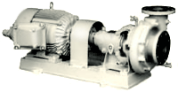
Single Stage Centrifugal Pump


Single Stage End Suction Centrifugal Pumps From Weinman Pumps


Single Stage, End Suction, Centrifugal Pumps, Weinman PumpsEnd Suction Centrifugal Pumps from Weinman are versatile, low cost pumps, engineered for virtually every phase of liquid handling. Heads to 260 feet, flows to 2000 GPM.

Advantages and Construction Features

Economy

Today...tomorrow...anytime... Single Stage End Suction Pumps from Weinman are your most economical buy. Lower in initial cost, they require a minimum of maintenance and operating expenses over the years.

Quality Construction
Every detail of precision workmanship plus finest materials contribute to Weinman's high standards of quality construction...your assurance of continuous, reliable pumping service.

Modern Design
Developed by experienced pump engineers thoroughly familiar with actual service conditions, Weinman Pumps feature the most modern and scientific hydraulic and mechanical design.

Efficiency
Single Stage End Suction Pumps from Weinman, particularly in smaller sizes, are more efficient than double suction pumps. Mechanical and hydraulic losses are reduced, resulting in higher operating efficiency.

Compactness
Single Stage End Suction Pumps from Weinman are particularly useful where installation space is limited.


http://www.process-controls.com

Single Stage, End Suction, Centrifugal Pumps, Weinman Pumps

Weinman Single Stage End Suction
Frame Mounted Composite Curve 1750 RPM


Weinman Single Stage End Suction
Frame Mounted Composite Curve 3500 RPM


Single Stage Centrifugal Pump


Single Stage End Suction Centrifugal Pumps From Weinman Pumps

End Suction Centrifugal Pumps from Weinman are versatile, low cost pumps, engineered for virtually every phase of liquid handling. Heads to 260 feet, flows to 2000 GPM.

Advantages and Construction Features

Economy

Today...tomorrow...anytime... Single Stage End Suction Pumps from Weinman are your most economical buy. Lower in initial cost, they require a minimum of maintenance and operating expenses over the years.

Quality Construction
Every detail of precision workmanship plus finest materials contribute to Weinman's high standards of quality construction...your assurance of continuous, reliable pumping service.

Modern Design
Developed by experienced pump engineers thoroughly familiar with actual service conditions, Weinman Pumps feature the most modern and scientific hydraulic and mechanical design.

Efficiency
Single Stage End Suction Pumps from Weinman, particularly in smaller sizes, are more efficient than double suction pumps. Mechanical and hydraulic losses are reduced, resulting in higher operating efficiency.

Compactness
Single Stage End Suction Pumps from Weinman are particularly useful where installation space is limited.

http://www.process-controls.com

Mach3 CNC Probe Tool


This kit includes the major components you need for a fully capable DC CNC system, perfect for the do-it-yourselfer who wants to save money and still have all the features of a more expensive off-the-shelf system. AjaxCNC has bundled together a fast, reliable DSP-based CNC CPU card (our "MPU11"), with a 15 amp 3-axis servo drive and PLC combo (our "DC3IO"), into a dead simple plug-and-play system optimized for use with Mach3 software. Not only that, we've taken all the work out of configuring your system: coolant, lube, spindle control, limits, and more have dedicated connections and are pre-programmed and ready to run.

http://www.ajaxcnc.com

Single Stage Centrifugal Pump

Centrifugal Pump Principles - sample_2


Self-Priming Centrifugal Pump
UHN series
(PAT.)

Outstanding self-priming performance even under extreme conditions

Top page
& Site map
Contact us


Self-Priming Centrifugal Pump

Patented in Japan, U.S.A., other


Bore

40-250mm

Total head

10-90m

Capacity

0.1-8m3/min


Standard centrifugal pumps have no self-priming capability and are incapable of pumping when water flow is discontinued in the suction pipe. The oval shaped self-priming pump has weak self-priming force at locations where back pressure is present, and the higher the pump head, the harder to self-prime the water.
The YOKOTA Self-Priming Centrifugal Pump has the same pumping capability for high head pumping as other centrifugal pumps, however its self-priming force is extremely strong at 60-90kPa (6-9m water column), which enables the pump to be used even under extreme conditions.

For suction pumping with outstanding self-priming power:

UHN type

For intake piping across embankments or long intake pipes:

Priming strengthened UHNS/UHNK types

For high density slurry:

Slurry resistant UHT type

For installation in places subject to submersion:

UHPR type with submersible motor


Features of the YOKOTA Self-Priming Centrifugal Pump

Outstanding self-priming power


The internationally patented water-air separating mechanism reaches a maximum vacuum of 60-90kPa (6-9m water column) and displays outstanding self-priming power.

No problem with suction of air during pumping


A large amount of incoming air can be separated and discharged during pumping. Even if pumping becomes subject to suction or mixture of air due to fluctuations of suction conditions, it continues pumping, constantly discharging air, and restores normal pumping operation as soon as suction conditions return to normal. Even continuous suction of air-containing water (i.e., gas-liquid two-phase pumping) is possible.

Low NPSH


Even if cavitation develops due to fluctuations of suction conditions such as water level, temperature, or vacuum level on the suction side, this pump can still continue its pumping operation. Therefore, this pump does not require allowance for NPSH, and enables stable pumping operation even under fluctuating suction conditions. It naturally shows outstanding performance for extraction from sealed (vacuum) tanks.

Simple structure without any inlet valve, No need for a foot valve


Due to its simple structure without any inlet check valve, it is robust and easy to maintain. Moreover, there is no need for installing a foot valve or an intermediate valve on the intake side under ordinary operating conditions.
Operation is also easy with no need for priming.

Intake piping across embankments or long intake piping is possible


Because of superior intake power, intake pipes can be installed across embankments.
Intake piping with long piping is also possible.

Outstanding pumping performance


This single-suction, single-stage centrifugal pump displays outstanding pumping performance in a wide range of specifications.

Large selection of models, Large selection of materials


This self-priming pump has an incomparably wide variety of models available for easy selection. Further, a wide variety of materials are available, including FC, CAC, SCS and YOKOTA's corrosion and wear resistant special stainless steel casting (YST), to meet the needs of various kinds of liquid.

Construction that can meet a wide range of specifications


Standard constructions include semi-open impellers for small pumps and closed impellers for medium and larger pumps.


The impeller has been improved to form ideal blades for high efficiency.


An oil bath lubrication system is adopted for bearings.


Maintenance is easy to perform because construction is simple and the number of parts in the water passage section is minimized.

Stable quality


All special material products are manufactured internally in a continuous process to ensure stable quality.


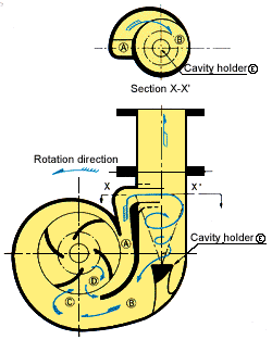
Principle of self-priming (PAT.)


The pump casing consists of a smaller passage and a larger passage forming a semi-double volute and a cavity holder in the discharge nozzle.

1.

Flow of circulation

During self-priming, the water discharged from passage A in the semi-double volute returns to the impeller through passage B-C, and is discharged again into passage A.

2.

Removal of bubbles


This recirculation flow mixes the water and the air in the center with intense vortex D within the impeller and discharges it into passage A.

3.

Water-air separation and exhaust


The water-air mixture is led from passage A to discharge nozzle B in a cyclonic state and automatically separated by centrifugal force, and then the water is recirculated through passage B-C. The separated air is then held by cavity holder E, and compressed and discharged.


http://www.aquadevice.com


Self-Priming Centrifugal Pump / Principle of self-priming  (PAT.)

Centrifugal Pump


CORROSION FREE CENTRIFUGAL PUMPS : :

TiTaN's centrifugal pump (radial flow, mixed flow, and axial flow) consist of rotating vanes, enclosed within a housing or casing, used to impart energy to a fluid through centrifugal force. The pump has two main parts: a rotating element which includes an impeller and a shaft, and a stationary element made up of a casing (volute or solid), stuffing box, and bearings.


centrifugal pump cross sectional view
Stuffing Box - A : :
Packing - B : :
Shaft - C : :
Shaft Sleeve - D : :
Vane - E : :
Casing - F : :
Eye of Impeller - G : :
Impeller - H : :
Casing wear Ring - I : :
Impeller - J : :
Discharge Nozzle - K : :
monel centrifugal pumps


Corrosion resistant radial flow pumps are centrifugal pumps in which the pressure is developed wholly by centrifugal force. In mixed flow pumps, the pressure is developed partly by centrifugal force and partly by the lift of the vanes of the impeller on the liquid. Axial flow centrifugal pumps develop pressure by the propelling or lifting action of the vanes of the impeller on the liquid.
titanium liquid ring vacuum pump
: : NON CORROSIVE LIQUID RING VACUUM PUMP : :


TiTaN's Liquid ring vacuum pumps are commonly used to handle wet gas mixtures (ie mixtures containing condensable vapors). The eccentric mounting of the impeller with respect to the casing results in increased spacing between the impeller blades at the inlet port and decreased spacing towards the outlet port.

As gas enters the inlet port, it is trapped between the impeller blades and the liquid ring. Then, as the impeller rotates, the liquid ring compresses the gas and forces it out the outlet port.


inconel centrifugal pump


: : NONCORROSIVE METERING PUMP AND DOSING PUMP : :

nickel centrifugal pump
Chemical liquids handling applications such as high-pressure additive injection in oil production and transferring thick, high-temperature, corrosive and abrasive liquids, are examples of the tough demands increasingly made for metering pumps used in the process and chemical industries. To meet these demands TiTaN developed superior quality chemical dosing pumps.


: : CHEMICAL PROCESS PUMPS & SPARES WE OFFER (design wise) : :


: : centrifugal pump (titanium, zirconium, nickel, monel, inconel)
: : water ring vacuum pumps (titanium, hastelloy, duplex, zirconium)
: : liquid ring vacuum pump (titanium , zirconium, cupro nickel, monel)
: : metering pumps (titanium Gr7, hastelloy, duplex, zirconium, nickel)
: : dosing pumps (titanium Gr 7, hastelloy, duplex, zirconium, nickel)
: : sealless pump (titanium , zirconium, cupro nickel, incolloy, inconel)
: : submersible pump (titanium, hastelloy, duplex, zirconium, monel)
: : vertical inline pump (titanium, hastelloy, duplex, zirconium, nickel)
: : pump spares (closed / open impeller, casing, sleeve, shaft, seal)
: : other pump spare (pump impeller, casing, sleeve, shaft, lock nut)


metering & chemical dosing pumps


: : PUMPS & SPARES (material wise) : :
: : PUMPS (application wise) : :


: : titanium grade 7 pump & impeller
: : tantalum pump (metering pump)
: : nickel pump (dosing pumps)
: : inconel pump (vacuum pump)
: : monel pumps (submersible pump)
: : zirconium pump (vertical inline type)
: : hastelloy pump (sealless pump)
: : incolloy pump & pump spares
: : duplex pumps & impellers, casing
: : speicial grade SS pump & sleeves
marine pumps : :
bromine feeder pump : :
sea water booster pump : :
sodium hypo pump : :
hypochlorite dosing pump : :
polymer feed pump : :
waste water handling pump : :
makeup pumps : :
fertilizer pump : :
ARP plant pumps : :


water ring vacuum pump


: : PUMP SPARES WE SUPPLY : : (we are the manufacturer & supplier of exotic metal pump spares)

: : pump impeller (open type impeller, closed type impeller) (titanium, zirconium, nickel spare)
: : pump casing, stuffing box (solid, rubber lined) (titanium, hastelloy, duplex pump spare)
: : pump shaft (titanium, zirconium, monel, inconel, hastelloy, duplex, cupro nickel, SS shafts)
: : pump sleeve, locknut, mechanical seals, base frame (tantalum, duplex, nickle spares)


Animated Engines, Two Stroke_files

File:Two-Stroke Engine.gif
No higher resolution available.
Two-Stroke_Engine.gif‎ (image/gif, 204 KB, looped, 8 frames, 4File:2-Stroke Engine ani.gif
No higher resolution available.
2-Stroke_Engine_ani.gif‎ (image/gif, 284 KB, looped, 36 frames, 0.4s


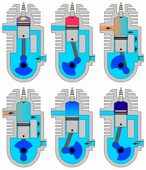
Intake
The fuel/air mixture is first drawn into the crankcase by the vacuum that is created during the upward stroke of the piston. The illustrated engine features a poppet intake valve; however, many engines use a rotary value incorporated into the crankshaft.
Crankcase compression
During the downward stroke, the poppet valve is forced closed by the increased crankcase pressure. The fuel mixture is then compressed in the crankcase during the remainder of the stroke.
Transfer/Exhaust
Toward the end of the stroke, the piston exposes the intake port, allowing the compressed fuel/air mixture in the crankcase to escape around the piston into the main cylinder. This expels the exhaust gasses out the exhaust port, usually located on the opposite side of the cylinder. Unfortunately, some of the fresh fuel mixture is usually expelled as well.
Compression
The piston then rises, driven by flywheel momentum, and compresses the fuel mixture. (At the same time, another intake stroke is happening beneath the piston).
Power
At the top of the stroke, the spark plug ignites the fuel mixture. The burning fuel expands, driving the piston downward, to complete the cycle. (At the same time, another crankcase compression stroke is happening beneath the piston.

http://commons.wikimedia.org

Translate

MECHANICAL DAE

Adhitz

payza

BidVertiser

odesk

The On Demand Global Workforce - oDesk

adBrite

Your Ad Here